Description
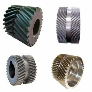
The commonly used steels for manufacturing inner planetary gears are quenched and tempered steel, hardened steel, carburized hardened steel, and nitrided steel. The strength of cast steel is slightly lower than that of forged steel, which is often used in gears of larger sizes. The gray cast iron has poor mechanical properties and can be used in light-loaded open-gear transmissions. The nodular cast iron can partially replace steel to make gears. The plastic gears are often used for light loads, and where low noise is required, the gear paired with it is generally a steel gear with good thermal conductivity.
Description
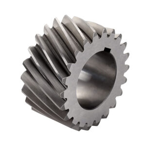
| Model Number | M3,M4,M5,M8,M12 and etc. |
| Material | Brass, C45 steel, Stainless steel, Copper, POM, Aluminum, Alloy, and so on |
| Surface treatment | Zinc-plated, Nickel plated, Passivation, Oxidation, Anodization, Geomet, Dacromet, Black Oxide, Phosphatizing, Powder Coating, and Electrophoresis |
| Standard | ISO, DIN, ANSI, JIS, BS, and Non-standard. |
| Precision | DIN6,DIN7,DIN8,DIN9. |
| Teeth treatment | Hardened, Milled, or Ground |
| Tolerance | 0.001mm-0.01mm-0.1mm |
| Finish | shot/sandblast, heat treatment, annealing, tempering, polishing, anodizing, zinc-plated |
| Items packing | Plastic bag+Cartons Or Wooden Packing |
| Payment terms | T/T, L/C |
| Production lead time | 20 business days for sample,25 days for the bulk |
| Samples | Sample price range from $2 to $100. sample express request paid by clients |
| Application | 1. Automatic controlling machine 2. Semi-conductor industry 3. General industry machinery 4. Medical equipment 5. Solar energy equipment 6. Machine tool 7. Parking system 8. High-speed rail and aviation transportation equipment, etc. |
In the future, gears are developing in the direction of heavy load, high speed, high precision, and high efficiency, and strive to be small in size, light in weight, long in life, and economical and reliable. The development of gear theory and manufacturing technology will further study the mechanism of gear tooth damage, which is the basis for establishing a reliable strength calculation method and is the theoretical basis for improving gear bearing capacity and extending gear life; the development is represented by circular tooth profiles; researching new gear materials and new gear manufacturing technology; researching gear elastic deformation, manufacturing and installation errors, and temperature field distribution, and modifying the gear teeth to improve the smoothness of gear operation, and the contact area of the gear should be increased when the gear is fully loaded, to improve the bearing capacity of the equipment.
Friction, lubrication theory, and lubrication technology are essential works in gear research. Studying the theory of elastic fluid dynamic pressure lubrication, promoting synthetic lubricating oil, and the valuable addition of extreme pressure additives in the oil can improve the bearing capacity of the tooth surface and improve the transmission efficiency.
Failure Form
1. Tooth surface wear: for open gear transmission or secure gear transmission with unclean lubricant, due to the relative sliding between the meshing tooth surfaces, some hard abrasive particles enter the friction surface, thereby changing the tooth profile and the backlash increases, so that the gear is too thin and the teeth are broken. In general, only when the abrasive particles are mixed in the lubricating oil the wear of the tooth surface abrasive particles will be caused during operation.
2. Tooth surface guling: for high-speed and heavy-load gear transmission, the friction between the tooth surfaces is large, and the relative speed is high, which causes the temperature in the meshing zone to be too high. Once the poor lubrication conditions, the oil film between the tooth surfaces will disappear. The metal surfaces of the two teeth are brought into direct contact, thereby causing mutual guling. When the two tooth surfaces move relative to each other, the more brutal tooth surface tears out part of the material on the softer tooth surface in the sliding direction to form a groove.
3. Fatigue pitting: when the teeth of the two meshing teeth are in contact, the contact stress between the tooth surfaces and the reaction force cause contact stress on the two working surfaces. Because the position of the meshing point is changed, and the gear is periodic Movement, the contact stress changes in a pulsating cycle. Under the action of this alternating contact stress on the tooth surface for a long time, small cracks will appear at the cutter marks on the tooth surface. Over time, this kind of crack gradually expands laterally in the surface layer. The teeth’ surface spalled with a small area, and some shallow fatigue pits formed.
4. Gear teeth broken: gears that bear loads during operation are like cantilever beams. When the periodic stress on the gear’s root exceeds the gear material’s fatigue limit, the crack will be generated at heart and gradually expand. When the remaining part cannot bear the transmission load, tooth-breaking occurs. Gears may also cause teeth to break due to the severe impacts, unbalanced loads, and uneven materials during work.
5. Plastic deformation of the tooth surface: The tooth surface is prone to local plastic deformation under impact load or heavy load. Thereby, the curved surface of the involute tooth profile is deformed.